Having looked at the literature of visual programming, and having created
some languages, we now pull back to make some observations about the possibilities
and limits of visual programming. In doing so, we will use software complexity
metrics as a starting point. We find that the complexity issue explains
some of the problems with visual languages and suggests both the limits
and possibilities of visual programming.
Our approach is to first examine textual complexity metrics. For each
well-known metric, we find the closest visual correspondence. Then we examine
previous work that has been done on graphic metrics. Finally, we suggest
a new graphic metric. This metric is used to compare the relative effectiveness
of graphic and textual representations, from which we draw some conclusions
on the effectiveness of the visual.
Software Metrics is a pragmatic field that arises out of attempts to
estimate the amount of time it will take to code and maintain software.
In the realm of software metrics, code is looked at the output of labor.
The complexity of a piece of software is thought of in the same way as
the complexity of an automobile - the number of parts and the nature of
the assembly may affect the amount of labor needed to create the end product.
Software metrics are often controversial. There are not many instances
in the literature of repeatable, scientific tests of metric predictions
versus actual results. Part of this is due to the large number of variables
involved in a software project that are not easily factored out. Also a
factor is the invisibility of software. In the domain of civil engineering,
it is easy to test whether a bridge has been completed. Yet in the domain
of software engineering, the end of a software project is more a matter
of declaration than fact.
The metric is computed by counting the number of lines of source code
in a program. It is based on the assumption that larger programs are more
complex and take longer to write. In a variant of this, only significant
lines of code are counted; white space and comment lines are suppressed.
Lines of code (sometimes referred to as LOC) are easy to measure automatically
- a simple filter that detects carriage returns in a text file can be used.
The lines of code heuristic assumes that all lines of a program are
equally significant. A complex mathematical expression will count the same
as a simple assignment. Three objections have been made to this heuristic.
The first is that programs of equal size may differ drastically in complexity.
The second is that the number of lines of code used to solve a particular
program can vary widely depending on the skill and style of the programmer.
The third is that this heuristic is only good after the fact, as software
professionals don't have a good track record of being able to predict the
lines of code needed to represent a specified problem. Yet for all these
objections, lines of code is the most used heuristic. Productivity measures
are periodically made on the number of lines of production source code
produced per year by the average programmer; this number is running at
the time of writing around 8000 lines per year.
The concept of a line of code is purely textual. There is no such thing
as a line in a graphic program. However, we can generalize lines of code
to pages-of-text, by picking an average number of lines of code per printed
page (say 60). It is then possible to create a related metric which we
call pages-of-diagram, corresponding to the number of 8 1/2 x 11
sheets taken up by a visual program representation when printed at a normal
magnification. This heuristic has the disadvantage of not differentiating
a very complex diagram from a very simple one (but neither does Lines of
Code). It has the advantage of being easy to calculate from the output
of any visual programming system.
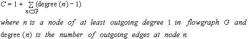
One of the better known and most graphic metrics is cyclomatic complexity,
defined by McCabe (1976). The metric can be defined in two equivalent ways:
the number of decision statements in a program + 1
or
for a graph G with n vertices, e edges, and p connected components,
v(G) = e - n + 2p
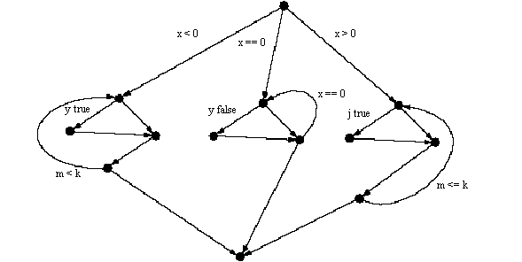
A code fragment and its corresponding flow graph are shown below:
if (x < 0)
        do {
                if (y)
                        b();
                m = c() * m;
        }
        while (m < k);
else if (x == 0)
        do{
                if (y ==0)
                        b();
                c();
        }
        while (x == 0)
else
        do {
                if (j)
                        b();
                m = c() * 2m;
        }
        while (m <= k);
Figure 7.1. Flow diagram for the above code.
This flow diagram has a McCabe complexity of 9 (there are 20 edges, 13 nodes, and 1 connected component; 20 - 13 + 2 = 9). The number can be calculated in three ways. The number of branches (ifs, whiles, fors) in the code can be counted and the sum incremented by one. From the graph, another way is to count the number of regions in the graph; in the above diagram there are 8 interior regions + 1 surrounding region.
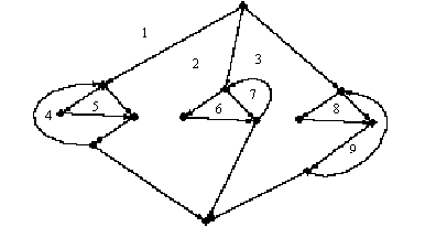 Figure
7.2. McCabe complexity by counting regions
Figure
7.2. McCabe complexity by counting regions
Finally, the number of branches can be counted from the graph. The McCabe
complexity C can be defined:
In McCabe's scheme, the complexity of an expression within a conditional statement is never acknowledged;
if((x = b * b + sqrt(sin(z) - 1)/ 3) > 1 * a)
is counted the same as
if (x > y)
Both add 1 to the complexity measure. Also, any complicated expressions
inside a non-conditional statement are not counted at all. A very long
straight-line program will have a McCabe complexity of 1.
There is no penalty for embedded loops versus a series of single loops; both have the same complexity.
The complexity measure is simple. There is no doubt that a large class
of programming errors occur around conditions and loops. There is also
no doubt that every condition in a program calls for extra testing, and
obviously complicates the writing, understanding, testing, and maintenance
of code.
It is also likely that most code tends to a uniform number of branches
per line of code. In other words, it may be that the number of branches
and the number of lines of code is highly correlated in a large class of
programs. Therefore, measuring branches is akin to measuring length. Defenders
of the lines-of-code heuristic use this argument to dismiss the McCabe
metric as extraneous. The counter-argument is that, while most programs
tend toward an average number of branches per line, the McCabe metric will
differentiate a simple straight-line program from a convoluted branching
program of the same length. It is also possible to argue that program length
and the number of branches in code are separate dimensions of what we may
call program complexity.
Many visual languages are based on flow graphs, and have branch points
on the graph, so the regions of the graph or the branch points can be counted.
Therefore the McCabe metric is a very natural graphic metric for any flow
graph-based language.
McCabe (1976) observes that "after seeing several of a programmer's
control graphs on a CRT one can often recognize 'style' by noting similar
patterns in the graphs" (p. 313). This implies that there may be other
formal aspects of the flow graph that may serve as indicators of code style,
well-formedness, ease of maintenance, experience of the programmer, etc.
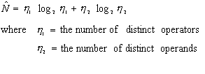
Next to McCabe's metric, the Halstead metrics are the most cited of
complexity measures. Halstead's writing on software complexity (1977) is
the most thought-provoking of the work cited here. However, the equations
of Halstead and their derivations are controversial. There are many articles
of experimental results confirming his equations on real code; there are
other studies that claim that his statistics and measures do not add up
- Card (1990) best summarizes and references objections to the Halstead
metrics.
Halstead's complexity measures are based on counts of operators and
operands in code. The size of code is the sum ![]() of
the number of operators
of
the number of operators ![]() and
operands
and
operands ![]() . This is
highly correlated to the number of lines of code, with the improvement
that more complicated lines will contribute more to the metric than simple
lines. Halstead's central observation on program length is that the number
of distinct, unique operators and operands can be used to compute a number
that approximates N:
. This is
highly correlated to the number of lines of code, with the improvement
that more complicated lines will contribute more to the metric than simple
lines. Halstead's central observation on program length is that the number
of distinct, unique operators and operands can be used to compute a number
that approximates N:
This equation suggests that given a specification, if we can figure
out how many distinct operators are called for (the functions we need to
build), as well as the number of distinct operands (the input and output
data), we can predict the total size of the program. Note that, in contrast
to McCabe, conditional statements are not distinguished from other statements.
This means a straight-line program may be shown to have equivalent complexity
to a branching one.
The next Halstead formula defines a quantity Volume that is the
length of a program times the minimum number of bits necessary to represent
the operators and operands:
As before ![]() represents
the number of operators and
represents
the number of operators and ![]() represents
the number of operands.
represents
the number of operands.
Halstead observes that in creating a program, we are making N choices
out of our vocabulary; in other words, we are choosing each operator and
operand in our program. We choose from our universe of h, the number
of different types, and in searching through this vocabulary, we will,
as a lower bound, have to make log h comparisons. The presupposition
is that human information processing is similar to computer processing,
and that in order to find the right operand, we need to traverse some sort
of search tree. With this assumption, Volume corresponds to the
number of mental comparison made in creating a program. While it is not
generally accepted that humans traverse search trees when searching for
the right operator or operand, it is clear that when programmers reuse
code, a certain amount of effort must be made understanding and searching
through the existing library, and that this effort is somehow related to
the number of things to be looked at.
Potential volume, ![]() ,
can be defined as the minimum program needed for a particular problem assuming
it can call already written code. The minimum number of operators is 2,
one for the function call and one for the assignment of the result, and
the number of unique operators or operands will be the same as the number
of operators or operands in the program, given the program is minimal.
,
can be defined as the minimum program needed for a particular problem assuming
it can call already written code. The minimum number of operators is 2,
one for the function call and one for the assignment of the result, and
the number of unique operators or operands will be the same as the number
of operators or operands in the program, given the program is minimal.
Halstead writes (1977):
The most succinct form in which an algorithm could ever be expressed
would require the prior existence of a language in which the required operation
was already defined or implemented, perhaps as a subroutine or procedure.
(p. 20)
This gives:
![]()
Program level is defined as the potential volume over the real volume:
![]()
The highest level program essentially says "do it", and everything
is taken care of in something already written at a lower level. The highest
level possible is 1. Halstead writes:
Clearly, it is usually easier to write a call or a procedure than it
is to write the procedure itself. From that point of view, a potential
language (L = 1) would be the easiest to use. But the concept of
a general purpose potential language implies that any procedure that might
ever by needed would already be available. Since the number of such procedures
is infinite, the task of becoming familiar with a mere list of them is
also infinite. Consequently, the implementation and use of potential, or
level one, languages is not feasible for general purpose work. On the other
hand, a special purpose potential language, such as a Saber for airline
reservations or the Job Control Language (JCL) for an operating system,
becomes quite feasible. The over-all problem here, then, is one of balancing
language implementation and user learning effort against the user savings.
(p. 26)
This can help explain some of the observations that we have made about visual languages. First, visual languages for special tasks exist and work well. Second, these specialized visual languages tend to be made up of predefined functions that do most of the work. This is equivalent in Halstead terms to a language with
L=1.
Any specialized language sitting on top of a general language can be constructed to essentially have an operator for all conceivable situations; this is very much desired in end-user languages, and all applications can be thought of constituting a language. Visual languages do well in this type of situation, as the visual helps structure the sometimes large set of possible operations. It is partially due to this that Visual Basic is so successful - there are hundreds of potential functions available at any time inside of a visual framework.
In order to compute a graphic Halstead metric, we need to be able to count operators and operands. In most visual languages, the nodes of a graph are equivalent to operators, and the arrows represent operands. In many cases the nodes are labeled with function names. (In a few graphic representations the situation is reversed: the operators are arrows and the operands are nodes. For example, in associative or semantic nets, "horse is a mammal" will be represented by the node horse, the relation isa, and the node mammal.)
A graphic Halstead N can be defined as
![]()
By analogy, we can recreate all of Halstead's equations as graphic metrics
by equating nodes with operators and edges with operands.
Levitin (1986) argues that the best and simplest metric is token count.
It is more accurate than lines of code, as it actually gets at the complexity
of lines. It is easily automatable, as most compilers will supply this
statistic as part of a run. And it is effectively the same as Halstead's
N.
We believe this argument, and will use Token Count, which we will call
Textual Token Count, in the future in evaluating programs.
There are two areas of potential lack of clarity in the metric. For
paired delimiters, it is unclear whether to count the pair as 1 or as 2.
Consistent with Halstead, we will opt to count a paired delimiter as 1.
Separators pose another potential problem. A comma counts as a token,
but white space does not count. In comparing some languages, this presents
a consistency problem. In most languages, foo(a, b) will result in a token
count of 5, but in Lisp, this expression is represented as (foo a b), for
a token count of 4. This problem is unique to LISP, and in the end LISP
representations are often longer by any metric than other languages because
of the strict nature of its prefix notation.
When we manufacture data for comparison purposes, we will insure that one separator is generated for each piece of data. So we will represent a list as (1, 2, 3), for a count of 6. In some cases, to generate a minimum textual representation, we will abbreviate
(1, 2, (3, 4)) to (1, 2 (3, 4)) for a count of 8.
Albrecht (1979) defines a metric oriented toward predicting the complexity
of the system from a functional specification. The metric is a weighted
sum:
function points =
the number of inputs * 4 +
the number of outputs * 5 +
the number of inquiries * 4 +
the number of master files *10
Inputs are any kind of input from a user to the system, except for inquiry
transactions.
Outputs are all outputs to the user, including printed reports, with
the exception of immediate inquiry responses. Simple error messages or
acknowledgments are not meant to be counted.
Inquiries are each input/response couplet where an input directly causes
an on-line output. No writes occur as part of an inquiry.
Files are unique files or groupings of data. Logical files are to be
counted rather than physical files. All machine readable interfaces are
to be counted as files.
In addition to the weighted sum, a questionnaire is used pertaining
to the functional complexity of the system, which can result in an adjustment
to the estimate of at most 25% in either direction.
This metric has the advantage of being a predictor of complexity before
a system is built-lines of code is only useful in retrospect, but function
points can be determined before any code is written. Albrecht also provides
some correlations of function points with lines of code (61 lines of code
per function point for PL/I, 110 for COBOL), and with work effort (30 hours
per function point on a 20,000 hour project coded in PL/1).
The metric is used mainly in the mainframe world, and is somewhat controversial,
as the counting of the above quantities is often open to interpretation.
However, it has a fairly wide following, as it provides a way of not only
estimating large projects before building, but also for estimating small
requests for modifications in the maintenance part of the software life
cycle.
Starting with a data flow diagram of the system, it is possible to approximate
a function point count by counting graphic elements on the drawing. Data
flow stores correspond to logical files. Lines to the stores correspond
to input. Lines from the stores correspond to output. Inquiries present
a problem, in that data flow diagrams do not specifically indicate inquiries.
One possible interpretation is to count the number of process nodes. We
therefore define the graphic function points of a data flow-diagram-defined
system as:
Graphic Function Points =
the number of edges from store nodes * 4 +
the number of edges to store nodes * 5 +
the number of process nodes * 4 +
the number of store nodes *10
In some ways, this graphic measure seems clearer and less open to interpretation
than the textual measure. However, the graphic measure assumes that the
data flow diagram is complete and correct. In a sense, the responsibility
for an accurate estimate is now placed on the analyst creating the diagram.
The graphic function point allows us to make some rough equivalents between diagrams and program labor. From the weighting above, on average a graphic element is worth about 6 function points. For PL/1, this implies that every graphic element on a data flow diagram will result in about 360 lines of code, or about 180 hours of programmer labor.
Glinert (1990) defines a hypothetical metric geared toward computing
the apparent iconic complexity to users of a program. The formula for the
apparent iconic complexity to user of a program P is:
![]()
![]() is the iconic window
size of the environment, calculated based on the average diagonal measure
of the screen and of the icons.
is the iconic window
size of the environment, calculated based on the average diagonal measure
of the screen and of the icons.
![]() is the iconic volume,
or the maximum number of icons the program may contain based on the number
of screen it uses.
is the iconic volume,
or the maximum number of icons the program may contain based on the number
of screen it uses.
![]() is the percentage
of operations which at run time cause a new screen page to be displayed.
The + 1 term is provided to avoid a multiply by zero.
is the percentage
of operations which at run time cause a new screen page to be displayed.
The + 1 term is provided to avoid a multiply by zero.
![]() and
and ![]() are
a pair of functions that measure according to Glinert (1990):
are
a pair of functions that measure according to Glinert (1990):
the extent to which the positive and negative qualities, respectively,
of the (graphical) program representation employed by the environment at
hand are mirrored in the given program P.
Glinert sees this function as being distinct for different programming environments. An example of the negative qualities for a particular environment is given by Glinert as:
![]()
where
![]() = the average number
of crossovers of control-of-flow paths on a single screen-page of program
P
= the average number
of crossovers of control-of-flow paths on a single screen-page of program
P
![]() = the average number
of elbows (bends in edges) of control-of-flow paths on a single screen-page
of program P
= the average number
of elbows (bends in edges) of control-of-flow paths on a single screen-page
of program P
The formula is not fully defined: Glinert writes:
the exponents a, b, c are greater than or equal to one, but not necessarily
constants.
The metric leaves a lot up to the interpretation of the measurer. It
calls for a pair of functions to be defined for each environment. The metric
is not meant to be used for comparison across environments.
This is the first metric to address what amounts to page faults in diagrammatic
languages - if we are watching a program run, how many times will the display
jump around? It also puts forward a countable measure of what we can call
diagram confusion: multiply the number of crossovers in a diagram by the
number of elbows, yielding a number that can be used to quantify the distaste
we often have for spaghetti-like diagrams. This last measure brings up
an interesting observation: Glinert notices that in his own language, the
Fibonacci program looks more tangled (and the confusion measure is higher)
than for a more straight-forward program. It raises the question as to
whether some algorithms are more tangled than others when represented visually,
and whether tangledness and recursion are related.
We wish to make use of the concept of a confusion metric, yet we seek a measure that is additive rather than multiplicative. We therefore define the following Glinert-derived metric:
graphic confusion count = number of crossings + number of elbows.
Graphic confusion will tend go up as the number of nodes and edges in
the graph increase, due to the nature of planarity; the larger the graph,
the more likely it is that a ![]() or
or
![]() subgraph will appear,
forcing crossings.
subgraph will appear,
forcing crossings.
We now look at a graphic measure coming from a different discipline.
The concern of Tufte (1983) is not with visual programming languages, but
with the representation of quantitative information on the printed page.
Tufte (1983) points out that in theory, by creating a fine grid on paper,
it is possible to make over 25,000 distinctions a square inch. In terms
of text, it is not unusual in a document with small print to show 185 characters
a square inch.
Tufte defines
![]()
His definition is oriented toward statistical plots. He documents the
density of statistical graphs in popular journals, showing that the majority
of sampled publications have rates of less than 10 per square inch. Of
those sampled, Nature magazine came in at a high of 48, where Scientific
American came in at 5.
Some outstanding examples, in the nature of maps, show rates ranging up to 250,000 per square inch.

Figure 7.3. A 1 inch by 6 inch strip of a map of France
showing regions.
Tufte estimates that there are 9000 pieces of statistical information per
square inch. From Tufte (1983).
Using the concept of Tufte, we propose for computer science a measure
of token density:
![]()
We create some of our own statistics, based on the diagrams throughout
this work. An average screen full of program text will have about 60 lines.
Each line will have 2 -4 tokens on average. There are about 40 square inches
on a display, giving a token density of 3 - 6 tokens per square inch. In
the average computer science diagram on a screen, there are about 20 tokens,
for a density of 2 tokens per inch.
Tufte's argument is that the more relevant information in a display,
the better. By this measure, the textual program is presenting more information
to the programmer than the diagram is, at the level of programming code.
Yet from the map example given above, the potential of the graphic to represent
information is actually higher than that of text.
It may be objected that density is not a good comparative measure, as density can equate with confusion. Certainly dense can be confusing, but sparse representation of a problem on a screen or page means that there are more screens and pages to look at or create in understanding or building a program. We return to the question of cognition at the end of the chapter.
In old-fashioned vector based displays, one measure of the complexity
of a drawing was the number of vectors needed to draw it. This is a low-level
measure, somewhat equivalent to counting characters in textual files. A
rectangle would have a stroke count of 4, even though it would most likely
be perceived as a whole.
Counting curves is problematic. For the sake of a standard, circles
can be counted as one stroke. Splines can be counted based on the number
of inflection points. Arrowheads are counted depending on how they are
drawn - open heads count as 2, closed heads count as 3.
This count is unambiguous, and will penalize those diagrams with many
elbows in edges or many cloud-like bubbles.
Minor decisions on the part of the designer, such as whether to use
square or circular nodes, can result in huge differences in the count.
Most diagrams are translated into a graphics language such as Postscript
before being transmitted to printers or screen displays. It is reasonable
to assume that the smaller the file, the simpler the diagram. The file
size can be counted in any of the ways discussed under textual metrics.
We define the size here to be the number of characters in the generating
program file.
This metric is related to stroke counting, but does not suffer the problem
of squares versus circles - generating programs often have macros which
make the representation of a square or a circular roughly equivalent. This
metric also provides a way of measuring conceptually simple diagrams that
may have many strokes - a regular grid may contain many lines, but can
be generated by a small program.
The complexity of a diagram can be defined as the length of the minimal
program that will generate it in some standard language. This provides
a tool with which what might be called the deep structure of diagrams can
be examined.
While we always can count the number of strokes or tokens on a diagram,
we often do not have access to the underlying generating program. Also,
different generating languages are at different levels and therefore will
be of different size in generating a program. Finally, many drawing packages
generate large standard headers and trailers. This means that the significant
part of the generating file may be a small percentage of the file length.
Therefore this metric fits more the theoretical than the pragmatic realm.
A graphic metric can be a useful way of describing diagrams and their relationship to textual representations. In this section we create two new metrics based on what we have learned from the preceding survey of textual and graphic metrics.
When creating a metric for textual languages, the items that can be
counted are relatively small. They include:
� number of characters
� textual operators and operands(Halstead)
� specific separators, such as line feeds (Lines of Code)
� Specific tokens, such as ifs, fors, whiles (McCabe)
When creating a metric for visual languages, there are many other characteristics
that can be looked at and counted:
|
|
|
|
|
|
|
|
|
|
|
|
|
|
|
Counting some of these things is akin to whether or not comments are
counted in source lines of code. Yet it is clear that there are many more
options available for characterizing diagrams.
In creating a metric, our goal is to come up with something that will
allow us to compare textual and graphic representations of computer programs.
The measure should be reproducible, and should handle a large class of
graph-based representations of computer programs and data structures. And
as far as is possible, diagrams that use slightly different conventions
to convey similar information should result in similar counts.
We will create two metrics. The first is a diagram class metric, characterizing
the complexity of the class of diagrams being created. The second is a
graphic token count, characterizing the complexity of a particular diagram.
The graphic token count of a diagram can be compared to the textual token
count of a textual representation of a program.
In order to create the heuristic, we first characterize diagrams as
being made up of nodes, edges, and labels. A node may contain other nodes
or diagrams, as in H-graph representations. A label may be compound - it
can made up of primitive labels, as when an edge is labeled with a boolean
condition.
Nodes, edges, and labels can be of different graphic types. A node is
of different graphic type from other edges when the diagram systematically
distinguishes a node from other nodes by use of some visual attribute,
such as shape, color, fill pattern, or size. An edge is of different type
from other edges when the diagram systematically distinguishes an edge
from other edges by use of some visual attribute or appendage, such as
line weight, fill pattern (dotted vs. dashed), arrowhead type, arrow tail
type, or color. A label is of different type from other labels when the
diagram systematically distinguishes a label by means of some graphic attribute
such as font , font weight, size, or capitalization.
The easiest way to distinguish the number of types is to consult a key
or legend for the diagram. When this does not exist, the number of types
must be ascertained by an understanding of the visual convention behind
the diagram, as in data flow diagrams, or by visual inspection.
Once we can distinguish the types of nodes, edges, and labels, the diagram
class complexity can be computed:
Diagram Class Complexity = number of node types +
number of edge types +
number of label types.
The diagram class complexity allows us to describe the complexity of
the conventions that are being dealt with in a class of diagrams. Within
a class of diagrams, the graphic token count is a measure of diagram object
complexity, yielding a number that is specific to a particular diagram.
It is essentially a count of all the nodes and edges and labels in the
diagram.
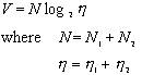
A node may contain other nodes. Containment is considered a form of
implicit edge. Each containing node is counted twice: once as a node, and
once as an implicit edge.
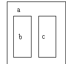
Two nodes may adjoin each other intentionally in a diagram. Adjoinment
is considered a form of implicit edge. When two nodes adjoin each other,
each node is counted as one, and the implicit edge is counted as one.
If a group of adjoining nodes is treated as a higher-level node, meaning
it is labeled or an edge is drawn from or to it as a whole, the group is
considered enclosed and the enclosure is treated as an extra edge for counting
purposes.
From the above discussion, the complexity of a diagram is:
Graphic token count = number of nodes +
number of edges +
textual token count +
number of enclosures +
number of adjoinments
contains(a, b, c)
 Figure
7.4. A textual and graphic representation of containment.
Figure
7.4. A textual and graphic representation of containment.
These representations both show represent the same relationship. The
first has a textual token count of 7. The graphic version also has a count
of 7 (3 nodes, 3 labels, and one implicit containment edge)
 Figure
7.5. Adjoinment
Figure
7.5. Adjoinment
This diagram has a graphic token count of 8 (3 nodes, 3 labels, and
2 implicit edges between the nodes.)
Given the textual token count and graphic token count metrics as tools,
we examine simple diagrams with the goal of determining how textual and
graphic methods of representation compare.
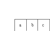
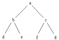
Minimal graphic expression of trees
A tree with n nodes has n - 1 edges. A tree with both
graphic nodes and labels for each node will have an graphic token count
of 3n - 1.
 Figure
7.6. Enclosed node representation of a tree.
Figure
7.6. Enclosed node representation of a tree.
By inspection, it is clear this tree of 7 nodes has a graphic token
count of 20. We can achieve minimal graphic token count by removing the
graphic nodes and leaving the labels in place to function as nodes:
 Figure
7.7. Open node representation of a tree.
Figure
7.7. Open node representation of a tree.
The graphic token count of such a diagram is 2n -1. For this example,
the graphic token count is 13. This removal of the graphic node and use
of the label in its place can only occur when the diagram has only one
node type.
The infix representation of this tree is:
(d, b, e), a, (f, c, g)
Removing redundant separators:
(d,b,e)a(f,c,g)
The prefix representation is:
a(b,d,e)(c,f,g)
The postfix representation is:
(d,e,b)(f,g,c)a
For all of the textual representations without redundant separators, the textual token count is 13, identical to the graphic token count. All nodes must be textually separated from all other nodes, either by a grouping operator or by a separator.
In some cases the textual count can be less than 2n - 1:
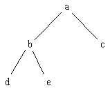 Figure
7.8. Unbalanced tree representation
Figure
7.8. Unbalanced tree representation
The prefix representation of this is:
a(b,d,e)c
which has a textual token count of 8 instead of the expected 9. This
is due to the bracket expression () functioning as a separator twice.
If we know other things about the tree, then the textual expression can be more compact. In the case of binary expression trees, infix notation provides an advantage over prefix and postfix notation:
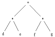 Figure
7.9. Binary Expression Trees
Figure
7.9. Binary Expression Trees
The infix representation of this is
(d * e) + (f *g)
or, if we assume normal precedence relations
d*e+f*g
Postfix notation yields
d,e*f,g*+
Prefix notation yields:
+*d,e*f,g
All except the second infix string have textual complexity of 9 - the
second infix string has complexity of 7 - obviously the lowest achievable
textual representation for a tree, as each node needs to be present at
least once.
Infix is in a sense a graphic convention - it collapses a tree onto
a line by keeping the central nodes of the tree in the center of the textual
expression. If the nodes of a tree are operators that can be distinguished
from leaves by symbolic convention, then in the case of binary trees operator
nodes will also function as separators.
We can conclude that the minimal textual representation of a tree will
range between n and 2n -1 for a tree with n nodes.
This number is less than or equal to the minimal graphic representation.
In terms of token density, it is clear that the textual representation is more dense. It can be argued that the graphic representation given can be tightened up; we present here for comparison the smallest resolvable examples of both textual and graphic representation of a 7 node tree structure:
(d,b,e)a(f,c,g)
as compared to:
![]() Figure
7.10. Smallest resolvable graphic tree representation.
Figure
7.10. Smallest resolvable graphic tree representation.
In this instance, the token density of the textual representation is
approximately five times greater than the graphic representation.
The textual representation will always be denser than the labeled diagram.
Assuming we are always dealing with diagrams with labels, the degree of
reduction is limited by the smallest font that can be resolved by our output
device (and our eyes) . This limit will be the same for textual and graphic
representations. In representing a diagram, nodes are connected by edges.
In order to represent an edge, it will need to be at least as long as the
span of the nodes it is connecting. So along both width and length, only
half the potential nodes can be shown. As a result, link-based graph conventions
have to be at least 4 times less dense than is potentially possible.
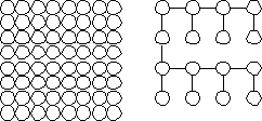 Figure
7.11. From a field of 64 possible nodes, 16 can be realistically used
in a tree or graph representation
Figure
7.11. From a field of 64 possible nodes, 16 can be realistically used
in a tree or graph representation
Without the restriction of having to label graphs, it does become possible to shrink a graph further down and achieve higher density:
![]() Figure
7.12. Smallest resolvable unlabeled graph representation.
Figure
7.12. Smallest resolvable unlabeled graph representation.
Yet, in most cases, a topological diagram without labels is not very
useful.
Tufte's data density measure shows the high potential of graphics to
transmit information. But there were two differences - metric scales were
used, so that each point represented quantitative information, and labels
were not necessary for each data element.
It may be objected that the textual representation is more compact, but is harder to comprehend. This argument has merit - there often a trade-off between compactness and comprehensibility. At the end of this chapter we will discuss ways of talking about the comprehension of diagrams. But here we point out that in the case of expression trees, the infix representation
d * e + f * g
is probably easier to grasp than:
 Figure
7.13. Binary Expression Tree.
Figure
7.13. Binary Expression Tree.
We can make a broader conclusion from this: attempts to create fully
visual languages where expressions are represented as trees will be fighting
the inherent effectiveness of infix representation, and will probably fail.
Mapping Graphs
The situation in mapping a graph to a textual representation is much
different. We consider proper graphs - all nodes have edges, and for a
graph with n nodes, there exist at least n edges, to avoid
the degenerate case of a tree.
 Figure
7.14. Simple graph representation.
Figure
7.14. Simple graph representation.
The graphic complexity a graph is e + n , where e = the number
of edges and n = the number of nodes. The graph above has a graphic complexity
of 10: 4 nodes and 6 edges.
One of the most common ways to represent this textually is with an edge list:
<a, b>, <b, c>, <a, c>, <a, d>, <b, d>, <c, d>
Each edge contains two nodes, a separator, and a bracket expression. This has a textual complexity of 24. The textual complexity of an edge list representation is 4e. An edge list will always be at least twice as large as the graphic representation:
e > n
2 e > e + n
4e > 2 * (e + n)
The most extreme case is that of a complete graph - for n nodes, a complete graph has
n(n-1)/2 edges. We solve for a multiplying factor x:
4n(n-1)/2 = (n + n(n-1)/2)x
x = 4(n -1)/(n+1)
The multiplying factor is effectively 4. Therefore, for an edge list
representation, the graphic representation is 2 to 4 times as efficient,
in terms of token count.
Another way sometimes used to represent a graph is an adjacency list: if the edges are only listed once, the list for this graph is:
a: <b, c, d>
b: <d, c>
c:<d>
The minimum number of rows needed to represent the graph is equivalent to the size of the vertex cover for the graph. Creating a convention more consistent with the edge list, we can convert this to:
<a, b, c, d>, <b, d, c>, <c, d>
We will use v = number of nodes in the vertex cover. Then the textual
complexity of an adjacency list represented in this way is 2e + 2v. Each
edge needs to appear as both a node and a separator, and each row in the
adjacency list appears as a node and a separator. The example above has
a textual complexity of 18: 2 * 6 + 2 * 3.
Any proper graph will have at least 2 nodes in the cover set. Therefore
the smallest representation for a graph is 4 + 2e.
At the other extreme, in the case of a complete graph of size n,
the vertex cover is of size n -1 . As an example for a complete
graph with n = 10, there are 45 edges, so the graph has a graphic
complexity 55. The textual token count is 18 + 90 = 108.
Solving for a factor x for complete graphs:
2 e + 2v = (e + n) x.
2(e + n -1) = x(e + n)
so x is effectively 2.
Best case is for a graph with a vertex cover of 2:
2v + 2e = x(n + e)
4 + 2e = x(n + e)
x = 2 (2 + e)/(n + e)
Making another best case assumption that the number of edges is close to the number of nodes:
x = 2/2e + e/2e
= 1 + 2/e
So for an optimal adjacency list representation, the graphic version
is 1 to 2 times more efficient. Also note that it is unlikely a graph will
be represented by a vertex-cover-optimized adjacency list, given the difficulty
of determining it. Most likely all nodes would be used, yielding a factor
of at least 2. In some cases, edges are represented twice on the adjacency
list, bringing the factor into the same range as that of the edge list,
around 4.
The above result suggests that the graphic representation of a graph
is more efficient than the textual representation.
Throughout this thesis examples of visual language have been presented.
At this stage we take some of the examples from previous chapters and analyze
them using graphic metrics.
 Figure
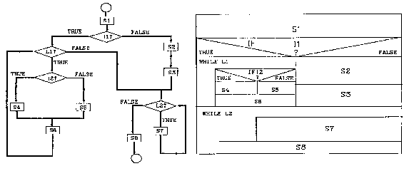
7.15. Nassi-Schneiderman and flow chart representation.
From Shu (1988).
Figure
7.15. Nassi-Schneiderman and flow chart representation.
From Shu (1988).
In this comparison of Nassi-Schneiderman and flow chart representation of the same situation, the graphic token count of the flow chart is 51 (14 nodes, 12 node labels, 17 edges, 8 edge labels) while the count of Nassi-Schneiderman is 53 (16 nodes, 22 node labels, 15 adjoinment edges). The token count is roughly equivalent, which suggests that linking and enclosure are equally effective in representing program fragments of this size.
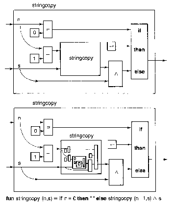 Figure
7.16. Recursive stringcopy representation from Reade(1989).
Figure
7.16. Recursive stringcopy representation from Reade(1989).
The graphic token count of the top diagram is 35 (9 nodes, 12 edges,
11 node labels, 2 edge labels, 1 containment edge). The textual token count
is 23. It takes more graphic tokens to explicitly show the relationships
between the elements of the statement, than it does with textual representation,
which takes advantage of the power of naming and the convention of infix
notation.
The major observation is in terms of density - the textual representation
is approximately 20 times more compact than the graphic representation.
In the bottom diagram, the graphic complexity theoretically goes to
![]() . In actuality, an extra
26 tokens are added. In the first recursion, labels and arrowheads are
dropped. In the second recursion, edges and some boxes are dropped. The
third level of recursion is abbreviated as a single box, into which no
more recursions can be dropped.
. In actuality, an extra
26 tokens are added. In the first recursion, labels and arrowheads are
dropped. In the second recursion, edges and some boxes are dropped. The
third level of recursion is abbreviated as a single box, into which no
more recursions can be dropped.
Containment conventions inevitably run into the barrier of resolution. Whereas link-based and adjoinment-based conventions allow expansion in two directions, the inward expansion of containment rapidly converges on the resolution of the screen or the printer. It is rare to see more than three levels of containment in a single diagram; the largest we have found is the system of Lakin:
 Figure
7.17. Lakin's deeply nested enclosures.
Figure
7.17. Lakin's deeply nested enclosures.
Enclosure is shown here down to 5 levels, about as far as the screen
resolution will permit. The lisp expression
(AND (NOT (NULL? Y))
(OR (AND (EQUAL? X (FIRST Y)) Y)
(MEMBER X (REST Y))))
has 24 textual units.
The graphic representation has a graphic token count of 21 (9 nodes,
6 labels, and 6 containment edges). This is an impressive count for a containment
convention; however, part of this has been accomplished through diagram
class complexity - there are 8 different node type out of 9 used nodes,
in addition to 1 label type and 1 edge type (containment). A diagram class
complexity of around 10 suggests that the diagram requires a high degree
of training to read.
There is a tradeoff - if we create a distinct node symbol for every operator in our language, we will reduce the graphic token count, while raising the diagram class complexity. In graphic user interfaces that make use of icons, this tradeoff is always apparent - once one knows what an icon means, their use is fast and convenient, but without understanding what the icons represent, the system is not usable.
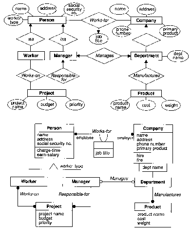
Figure 7.18. Entity-relationship modeling and Object-Oriented Modeling from Rumbaugh et al (1991).
In another illustration of type complexity, the classical form of entity-relationship
diagram is compared to an Object Modeling Technique Diagram. The diagram
class complexity of the top diagram is 8 (3 nodes types, 2 edge types,
and 3 label types). The type complexity of the bottom is 15(5 explicit
edge types, 3 implicit edge types, 2 explicit node types, 2 implicit node
types, 3 label types).
The high type complexity lessens the graphic complexity, and is noticeable
from quick inspection. Even though the diagram appears less complex, it
contains more information. The cardinality of relations, as well as some
of the operations and roles, are defined in the bottom diagram but not
in the top diagram.
The graphic count for the ER diagram is 93 (31 nodes, 29 labels, 32
edges).
The count for the OMT is 71 (16 nodes, 34 labels, 9 edges, 12 implicit edges). The Person Object is conceptually equivalent to:
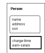 Figure
7.19. Enclosure diagram-equivalent for OMT notation.
Figure
7.19. Enclosure diagram-equivalent for OMT notation.
as links are intended to be between the entities, not the subdivisions.
The middle subdivision has a different node type, for attributes, and the
bottom subdivision has another implicit type, for operations. The types
are differentiated in the diagram by relative spatial location, as can
be seen by the empty entity title in the unnamed association between Company
and Person.
 Figure
7.20. Large data flow diagram from Gane (1979).
Figure
7.20. Large data flow diagram from Gane (1979).
The above diagram, originally a full page, is shown as an example of
the limits of what can be displayed with labeled graphs - the count is
271 (32 nodes, 52 edges, 187 labels). In terms of a graphic confusion,
we count 7 crossings and 28 elbows for a sum of 35. Token Density for an
80 square inch area is 3 per square inch.
Compare this with 40 square inches of source code reduced
#include <stdio.h>
main(argc, argv)
int argc;
char *argv[];
{
FILE *fp;
char buf[1000];
char combuf[1000];
char *pbuf;
char *pcombuf;
int i;
pbuf = buf;
pcombuf = combuf;
for (i = 1; i < argc; i++)
{
sprintf(pcombuf, "%s ", argv[i]);
pcombuf = combuf + strlen(combuf);
}
*pcombuf = NULL;
i = 0;
while ( (buf[i] = getc(stdin)) != EOF)
{
if (buf[i] == '\n') buf[i] = ' ';
i++;
}
buf[i] = NULL;
strcat(combuf, buf);
system(combuf);
}
This has a count of 140, or about the same density as the diagram. Yet
the text will resolve on a low-resolution screen, while the image will
not.
 Figure
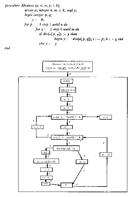
7.21. Program and equivalent flow chart from Pratt (1971a).
Figure
7.21. Program and equivalent flow chart from Pratt (1971a).
It is clear from this diagram that, in converting source code to flow
chart form, the number of tokens increase, and token density decreases.
Each statement in the source appears, with minor differences, in the flow
chart. In addition, the flow chart adds 20 nodes, 21 edges, and, in this
case, 21 edge labels, and one containment edge.
Note also the nature of the flow chart graph. This is a fairly typical
case - almost all nodes have only one outgoing and incoming edge. There
are only two backedges. From our earlier analysis, graphic portrayals only
come into there own when a graph is denser - yet most program code produces
very sparse graphs.
 Figure
7.22. String grammar equivalent for a complete 4 node graph. From
Gonzalez(1978).
Figure
7.22. String grammar equivalent for a complete 4 node graph. From
Gonzalez(1978).
This figure shows the difficulty with attempting to generate a proper graph from a grammar. Grammars work well with trees, for obvious reasons. But with graphs, we see that the token count of the string is 30, while for the graph it is 10.
 Figure
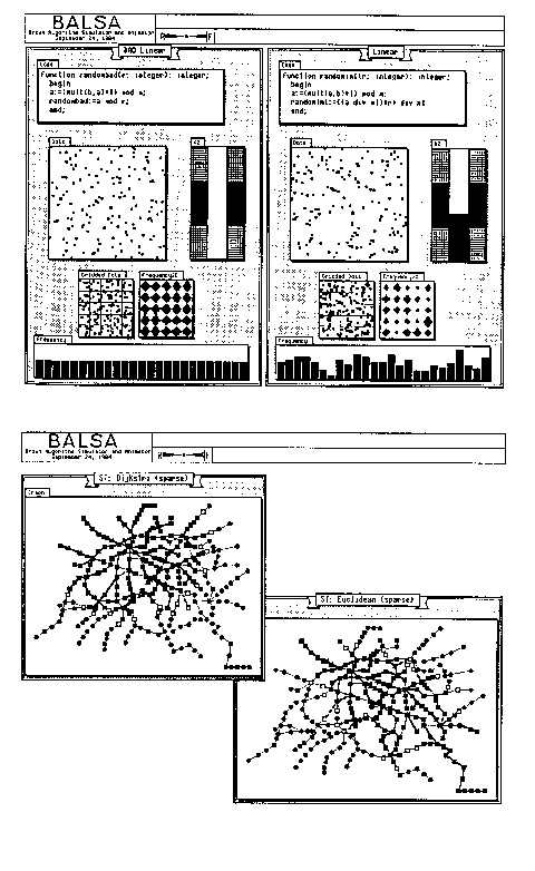
7.23. Two examples of Balsa program visualization. From Brown(1987).
Figure
7.23. Two examples of Balsa program visualization. From Brown(1987).
Balsa is an example of effective communication. In the top figure, the quantitative graphs would need to be represented with many hundreds of lines of statistics, and not have the same effect. In Tufte's terminology, the data density is very high. In the bottom graph, the visual is also very effectively used - the graph figures are unlabeled a high degree of graphic token density that could not be duplicated using text.
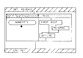 Figure
7.24. Matwin's Prograph list reversal.
Figure
7.24. Matwin's Prograph list reversal.
reverse(x)
if (nonempty(x) is TRUE)
return(append(reverse(rest(x)), first(x)))
else return(NIL)
Prograph makes heavy use of enclosure - here the count is 25, many in
implicit edges, very close to the textual representation, counting at 25
also. It is a good statistic, and implies that the language may be making
good use of conventions.
 Figure
7.25. Programming in Pictures. Raeder (1984).
Figure
7.25. Programming in Pictures. Raeder (1984).
In Raeder's thesis, the graphic display uses 22 tokens, ignoring the
date information, while the text representation of the function, shown
on the bottom left, uses 7 text tokens Also, the ratio of surface used
from the graphic to the textual is very large - at least 2 orders of magnitude.
 Figure
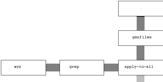
7.26. Searching for a string in all files.
Figure
7.26. Searching for a string in all files.
The graphic token count here is 15. A possible text representation of the function is:
apply_to_all(curry(grep(xyz)), genfiles(.))
The textual count is 11, and the density is far greater. Any tree-like
visual language can be converted easily into a textual form in the same
way this one was. The textual language will always be more compact.
However, the encoding of stream types in the edge patterns is lost.
More importantly, the intuition about a stream of data and functions is
gone in the textual version. The value of this intuition is difficult to
quantify. But we can quantify operations to build the function. Assuming
selection from a set of already-build functions, each function must be
selected and dragged to the appropriate spot. So for each function, 2 operations
must be made, or 10 operations to build the program. In order to type the
above string, 44 characters must be typed. For a good typist, the amount
of time to type in the string is probably about the same as to select and
drag the functions - but many more operations are being performed by the
typist, and many more errors may be introduced.
Textual representation here is more compact. But, given the limited universe of functions that must be chosen from for this shell-like language, the visual interface is a viable way of building simple small functions.
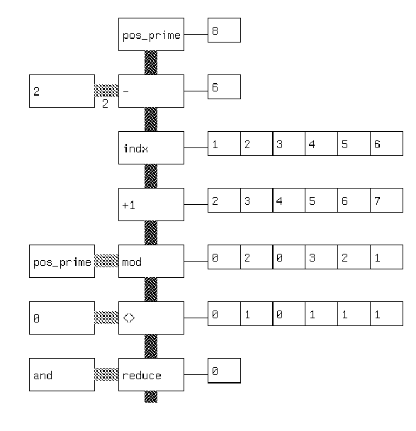 Figure 7.27. Visual APL version of a prime number checker.
The textual version of this in prefix notation is:
(and/ (<> 0 (mod n (+1 (indx (- n 2))))))
The textual count is 17. The graphic count is 35, not including the
output strings. Here the benefit of the language is pedagogical - by showing
output strings, it allows the results of long strings of operators to be
made evident. From a density standpoint, a textual representation is much
more compact and probably much more likely to be used by the programmer
adept at APL. A novice APL programmer might choose the graphic representation
to understand the language.
This suggests that visual languages may be important as learning tools
and as visualization tools for already built programmers. As much programming
is done by novices, this domain may be relatively large.
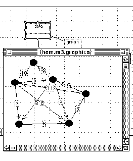 Figure
7.28. A weighted graph input interface.
Figure
7.28. A weighted graph input interface.
For defining a weighted graph, our analysis says nothing will be more effective than a graphic representation. Here all the nodes and edges can be seen as numbers are entered in, and the overall token complexity of this graph is 28. The generated text representation has many more tokens than this graphic representation: it is a weighted adjacency matrix with 78 tokens.
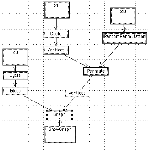 Figure
7.29. A program to generate a random graph.
Figure
7.29. A program to generate a random graph.
The textual equivalent of this program is:
ShowGraph[Graph[edges[Cycle[20]], Permute[Vertices[Cycle[20]],RandomPermutation[20]]]]
The graphic token count is 35. The textual token count is 21, and is
much more compact. In addition, the Mathematica textual language allows
for much general flexibility that cannot be expressed succinctly graphically.
A graphic visualization of an already built Mathematica function might
be useful. Likewise, a graphic tool kit that couples interactive input
and simple program construction for specific domains would be useful. Yet
for general work the textual version with graphic output is probably optimal.
In the previous chapter, Buhr's notation was discussed at length. Here, we take some of these conventions and analyze them for graphic complexity alongside the program text they are designed to represent.
 Figure
7.30. Buhr notation for a select statement. From Buhr (1984).
Figure
7.30. Buhr notation for a select statement. From Buhr (1984).
In this diagram, from Buhr (1984), the graphic and corresponding source
code stub are together. The graphic token count is 12. The textual complexity,
not counting the comments, is 22. Given an understanding of Buhr conventions,
the two communicate roughly the same amount of information in roughly the
same amount of physical page.
In a larger example, office activity is modeled:
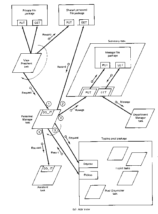 Figure
7.31. Buhr diagram for an office environment. From Buhr(1984).
Figure
7.31. Buhr diagram for an office environment. From Buhr(1984).
The graphic object count of this is high: 110. Buhr provides some code
for a small area of the diagram surrounding the Vice-President task:
task body VICE_PRESIDENT is
...
begin
        loop
                PRIVATE_FILE.GET(...);
                PRIVATE_FILE.PUT(...);
                PERSONNEL_FILE.PUT(...);
                PERSONNNEL_MANAGER.DO_IT(...);
        end loop
end VICE_PRESIDENT;
The textual complexity of this is 35.
The graphic representation communicates about the same amount of information in a about twice as much physical space, but with additional information that can be used to generate stubs for private file package, the shared personnel file package, and the Personnel Manager package.
The general impression from the counts is that Buhr notation is efficient
in communicating information. As it stays at the system design level, where
structures are graph-like, and avoids the portrayal of expression information,
the notation uses the potentials of the visual well.
 Figure
7.32. Buhr MachineChart representation of a reactor.
Figure
7.32. Buhr MachineChart representation of a reactor.
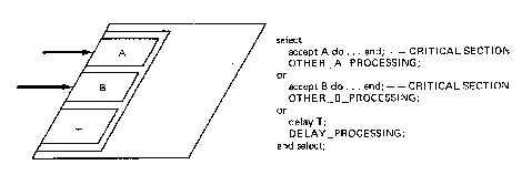
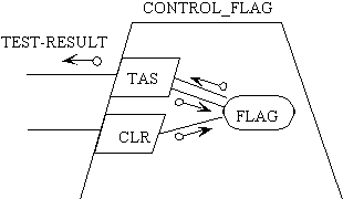
The corresponding code for this is:
type FLAGTYPE is range 0..1;
task CONTROL_FLAG is
        entry TAS (TEST_RESULT: out FLAGTYPE);
        entry CLR;
end CONTROL_FLAG;

task body CONTROL_FLAG is
        FLAG:FLAGTYPE;
        begin
                loop
                        select
                                accept TAS(TEST_RESULT: out                                                          FLAGTYPE)
                                        do TEST_RESULT := FLAG;
                                        FLAG := 1; end;
                        or
                                accept CLR
                                        do FLAG := 0; end;
                        end select
                end loop
        end CONTROL_FLAG
The diagram has a complexity of 19. The program has textual complexity
of 106. Here the program obviously contains more information than the diagram
- the diagram cannot show the actual setting of the flag. The diagram communicates
clearly the structure of the code, but not the details about operations
and sequences.
Buhr (1990) writes
Graphics is a useful design abstraction but text may be more appropriate in some cases. ...a textual language was needed for defining details of function: including data manipulation and the evaluation of conditions, that are difficult to define graphically. Examples of places where text is appropriate are the agendas of engines and the enabling conditions and actions performed by state machines.
This agrees with much of what we have been able to determine through
textual and graphic metrics. Buhr shows how a language, based on the data
types of SETL, can be used together with graphic representation: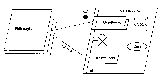 Figure
7.33. Overview of Dining Philosophers from Buhr (1990).
Figure
7.33. Overview of Dining Philosophers from Buhr (1990).
 Figure 7.34.
Detail of Dining Philosophers with SETL-like textual code.
From Buhr(1990).
Figure 7.34.
Detail of Dining Philosophers with SETL-like textual code.
From Buhr(1990).
The simple diagram. with a graphic token count of 29, can be seen as
a structure for more complicated conditions, with a textual complexity
of 192. The textual language contains no structural constructs, so both
the diagram and the text are needed to produce a program. The overall density
of this is very high - 6 tokens/square inch, suggesting that Buhr's thinking
allows for both visual thinking and high density in the programming environment.
So far we have been presupposing that windowing systems form the base
for visual programming systems. Here we explore an alternative graphic
user interface, Pad (Perlin 1993).
The Pad system creates a two dimensional landscape, so that all data
items have a coordinate in space. This means it is possible to get a spatial
sense of a document or a set of documents - to take advantage of the knowledge
that something is, say, in the upper right hand corner. Such spatialization
has been used to good effect in commercial interfaces such as the Macintosh
Finder as a way of creating the sense of a desktop. Yet Pad goes much further
with this concept. In contrast to the Macintosh finder, where a file must
be opened before it is read, in Pad the file is more like a piece of paper
on the desk - it is always visible. It may not be fully legible, but by
zooming continuously on any part of the landscape, it is possible to read
what from a distance might have been the overall shape of a text block.
As an improvement over an actual desktop with paper on it, the electronic
desktop space can have unlimited resolution - text annotating a memo can
be reduced to very small paragraph under a sentence in a document, and
the annotation can in turn be annotated with a another very small paragraph
underneath a sentence of the annotated text. Unlike hypertext systems,
in which there is usually no sense of Euclidean space, here the annotations
exist in the two dimensional space. Links are obvious from proximity, and
hierarchy is obvious from size.
The system supports multiple portals, which are essentially magnifying
glasses. These portals make it possible to look at a document from multiple
resolutions simultaneously: 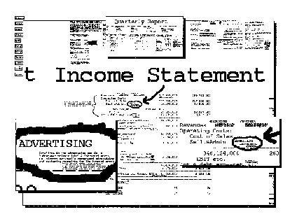 Figure
7.35. A company balance sheet in Pad. From Perlin (1993).
Figure
7.35. A company balance sheet in Pad. From Perlin (1993).
In this example, a company's balance sheet, which normally would be
split across many pages, is shown represented as a large blotter. More
detail can be acquired by zooming into the document. Three portals show
views distinct from the overall screen - the first view on the top shows
the entire document at low resolution. The second view on the right shows
some detail on the sheet, and the view on the left shows even more detail.
Much of Pad's power comes from dynamics. An image can be zoomed in on
continuously in real-time. The following sequence suggests the way one
may move into a document:
![]() Figure
7.36. Overview and detail of a document from Perlin(1993).
Figure
7.36. Overview and detail of a document from Perlin(1993).
Applying metrics to these images is difficult. If textual token counting
is used, only legible text can be counted, and the final count will indicate
a low token density. If graphic token counting is used, then it is unclear
how to count the illegible text - is every connected component counted
as a token, even if it is an artifact of subsampling? This situation can
be portrayed graphically by comparing the low resolution version of part
of the image on the left with its much higher resolution version on the
right. Both images have been scaled to be the same size:
![]() Figure
7.37. Extracts from the previous figure.
Figure
7.37. Extracts from the previous figure.
The image on the left has 33 connected components. The image on the
right has 59 connected components - 75 characters, some of which have bled
together. Yet, in counting the image on the right, we would apply the textual
token count metric, and count the number of words - 19. The numbers do
not seem comparable: it is obvious the image on the right communicates
much more information than the image on the left. A linguist would point
out that, as soon as the words become legible, they function as stimuli
and trigger associations in our internal semantic network.
Yet there is some information in the image on the left. It is possible
to see that five lines of text are represented. The number of words in
the paragraph can be estimated to within a factor of 2. And if we have
seen the text before, the shape of the paragraph may be enough to allow
us to recall the meaning. We propose that a low resolution paragraph be
considered equivalent to a textual token of 1, because, like the node of
a graph, it provides only locational and relational information.
As a paragraph is being zoomed in on, the local token count will jump
by one or two orders of magnitude at the instant where the text suddenly
becomes legible. (The overall token count of the image may possibly remain
the same, as when zooming, already resolved areas of the picture may disappear
from view on the boundaries of the image.)
The token count of a snapshot of a document in Pad is less important
than the token count over time. In a continuous zoom environment, the question
is really one of how large a space can be explored in a finite amount of
time. It is not obvious that, for text, Pad will prove more effective than
a quick scan of paper documents.
Our comparisons of the representation of trees and graphs suggests that
the value of Pad may be greatest in the representation of diagrams rather
than text.
Earlier we pointed out that topological graphs can possess a high graphic token count when drawn small - yet are not very useful, as without labels very few inferences can be made. The continuous zoom and portal capabilities of Pad make a big difference in the potential uses of topological graphs. An H-graph structure can actually be represented as a set of graphs physically contained within nodes:
![]() Figure
7.38. Directly nested H-graphs.
Figure
7.38. Directly nested H-graphs.
While labels on the contained graph would not always be visible, they
would appear as the image is zoomed in on. The above image has a relatively
high token count - 71 - and a very low confusion count - 0. Whereas the
confusion count of a graph with 25 nodes would normally be high, the hierarchy
of an H-graph can be used to reduce planarity problems in representing
relationships.
When the H-graph is zoomed in on, the jumps in local token counts are smaller than with text. In the worst case, every node and edge has a label that simultaneously become visible - at that instant, the token count doubles.
Pad might form the basis of a programming interface. Code maintenance involves working through hundreds of thousands of lines of code and documentation trying to find the source of a problem. A system that can combine graphic and textual documentation with source code could make a big difference in the maintainability of code. And making more use of diagrams, it is not difficult to imagine that a complex flowgraph for a computer program can be seen overall and, where labels are needed, a higher resolution portal could be created.
![]() Figure
7.39. Flowgraph representation using directly nested H-graphs.
Figure
7.39. Flowgraph representation using directly nested H-graphs.
The actual source code for each node could appear within the node itself.
Most of this chapter paints a fairly bleak picture of the power of graphic
representations compared to textual representation. We look here at some
of the advantages of the visual that do not show up in a density metric.
First, we invite the reader to try the following problem:
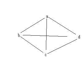
Given the following edge list, how many steps is node a from node b?
<<a, c>, <a, e>, <b, d>, <c, e>, <e, d>>
Now try this:
Given the following diagram, how many steps is node a from node b?
![]() Figure
7.40. Test graph.
Figure
7.40. Test graph.
In order to figure the question out from the textual representation,
one must scan the list and try out a few dead ends before finding the shortest
path is <a, e, d, b>. But in looking at the graphic representation,
it is possible to sense what the pattern is. For a computer program, the
situation is analogous - it would be faster to search a pointer representation
of the graph with parallel processors than it would be to scan a list.
The work of Anderson (1983) on cognition distinguishes between spatial
images, temporal strings, and abstract propositions, claiming there is
evidence of all three forms being used in human cognition. This work represents
a change of viewpoint, as prior to the work of Kosslyn (1980) documenting
the use of internal imagery, Anderson, with many other psychologists following
him, believed that all cognition could be explained in terms of abstract
propositions.
Nadin (1984) makes the distinction between sequences and configurations.
Configurations derive their power from their ability to seen all at once.
He also points out the drawback of the visual:
the concreteness of the image renders it incapable of attaining the level of self-expression (meta-level).
This is in fact the problem we saw in chapter 2: there is no satisfactory
graphic expression of recursion. Self-reference needs the power of naming,
which is not a visual concept.
Yet for the transitive closure problem shown above, no textual representation
will allow us to process the information as well.
We saw the visual work well on the creation of weighted graphs, as well
as on the graph-like structures of high-level system design. We saw that
the visual is even efficient in information terms in the expressions of
graphs. It is those things that we can speak of as being spatial, configurational,
that seem to work best with graphic representation.
Computer programming involves many different kinds of thinking. There
is a sequential mode of thought, especially in imperative languages. There
is a very abstract, propositional form of thought, especially in the use
of recursion or generics. And there is a spatial mode of thought, concerned
with places and relations between different components.
It is difficult to know what is going on in the mind of a programmer. But if the sequential, the symbolic, and the spatial are all used in programming, as the work of Anderson implies, it suggests that programming activity might need more than one language in more than one modality. Certainly a visual programming language alone will not obsolete the need for textual languages. The textual representation is the more powerful for general programming. But for other aspects of the programming activity, both our experience and our measurements suggest that graphic representation is useful.