 Figure
6.1. Buhr package and task notation.
The emphasis of this work up to now has been on the representation of
small programming problems. This chapter looks at problems related to system
design.
The system notation used in this chapter is Buhr's design notation.
His original notation, referred to as Buhr diagrams (1984), is well-understood
and accepted in the system design community. His later notation, MachineCharts,
(1990), is less well-known. MachineCharts are designed to address time-based
issues of complex system design, and for that reason contain many interesting
visual conventions for representing sequences and interactions. Buhr's
work is most closely linked with the programming language Ada, but contains
many constructs that don't map to Ada 83. Ada 9X contains structures anticipated
by MachineCharts, but also contains concepts that are difficult to express
in Buhr notation.
As a way of understanding the power of visual techniques in system design,
we look at Buhr notation as it exists, and attempt to apply it to Ada 9X
constructs. In some cases we propose extensions or changes to the MachineChart
notation.
Buhr (1984) created a notation for Ada programming that allows for the
internal and external structure of packages and tasks to be represented
in graphs. He writes:
Our pictorial notation provides a hardware-like metaphor for systems as collections of black boxes connected together by plugs and sockets.
Throughout his work there is an emphasis on mechanical or electrical analogs for computer programs. He differentiates the black boxes into the Ada language constructs of tasks and packages:

The notation emphasizes the interface points, the sockets through which
data and control flow:

Figure 6.2. Sockets in a task.
In the above diagram, nested boxes are used to show the alternate selections possible by the server task in response to requests from clients.
The text equivalent of figure 6.2 is:
select
        accept A do ... end
        -- other processing
or
        accept B do .. end
        -- other processing
or
        delay T;
        -- DELAY PROCESSING
end select;
In MachineCharts Buhr (1990) changes his terminology. Black boxes are
differentiated into boxes and robots, instead of packages and tasks.
Buhr makes a distinction between an active robots, called actors, and
passive robots, called reactors. Reactors model objects that provide mutual
exclusion. Reactors can serve as glue between actors to allow for asynchronous
communication. And reactors may be implemented without the overhead of
mechanisms such as rendezvous.

Figure 6.3. MachineChart distinctions.

Figure 6.4. A visit from an engine
in an actor robot to the button of an actor robot.
Visits take place through buttons on black boxes. Procedure calls, RPC
calls, and Ada rendezvous can all be considered visits; Buhr is generalizing
his notation so that it can be applied to any time-based problems implemented
in any language.
The following is an example from Buhr of how reactors can be used:

Essentially, the trapezoid-shaped box signifies that mutual exclusion
is assured. The corresponding Ada code for this is:
type FLAGTYPE is range 0..1;
task CONTROL_FLAG is
        entry TAS (TEST_RESULT: out FLAGTYPE);
        entry CLR;
end CONTROL_FLAG;

task body CONTROL_FLAG is
        FLAG:FLAGTYPE;
        begin
                loop
                        select
                                accept TAS(TEST_RESULT: out                                                          FLAGTYPE)
                                        do TEST_RESULT := FLAG;
                                        FLAG := 1; end;
                        or
                                accept CLR
                                        do FLAG := 0; end;
                        end select
                end loop
        end CONTROL_FLAG
Buhr has added timing diagrams to his notation system to help visually
present the behavior of software machines. The following presents an expected
visit scenario for the test and set example above:

Timing diagrams are normal in engineering, but are uncommon in software design. Yet the diagram presents a scenario that is difficult to express textually. The best textual representation is a table as follows; note that such a representation makes it very difficult to get a sense of user overlap:
Scenario Intended Result
User 1 CLR
User 1 TAS Flag = 0
User 2 TAS Flag = 1
User 2 TAS Flag = 1
User 1 CLR
User 2 TAS Flag = 0
Buhr suggests that a tool could be developed that could generate expected
visit timing diagrams as output from interacting with a structure chart.
Buhr's MachineCharts conventions were created prior to the Ada 9X mapping
specification. Nevertheless, the visual conventions surrounding reactors
map easily onto the proposal in Ada 9X for Protected Records. In Ada 83,
the only way to achieve synchronization is through the overhead of a rendezvous.
In order to reduce the overhead for real-time programming, Protected Records
are defined so they can be implemented as efficient conditional critical
regions. The specification of the record distinguishes between functions,
procedures, and entries that may block. Intermetrics points out that these
distinctions are essential for design and analysis.
Here is an example of a textual protected record from the Ada 9X Mapping
Specification, followed by a visual representation using Buhr's MachineCharts.
protected type
COUNTING_SEMAPHORE(INITIAL_COUNT : INTEGER := 1) is
function COUNT return INTEGER;
procedure RELEASE;
entry ACQUIRE;
private record
CURRENT_COUNT : INTEGER := INITIAL_COUNT;
end COUNTING_SEMAPHORE;
protected body COUNTING SEMAPHORE is
function COUNT return INTEGER is
begin
return CURRENT_COUNT;
end COUNT;
procedure RELEASE is
begin
CURRENT_COUNT := CURRENT_COUNT + 1;
end RELEASE;
entry ACQUIRE when CURRENT_COUNT > 0 is
begin
CURRENT_COUNT := CURRENT_COUNT - 1;
end ACQUIRE;
end COUNTING_SEMAPHORE;

The Protected Record is represented as a trapezoid, a reactor. Current_count,
labeled as c_count, is shown as a variable that is updated by Release and
Acquire. The function Count returns this number on a query.
The visual representation makes it easy to differentiate between entries,
functions, and procedures. The large dot outside the Acquire button indicates
a waiting position in the design; it is possible requests are queued waiting
for the semaphore. In the case of Ada, this indicates that Acquire is an
entry. Data flows are indicated by small arrows with a circle at the tail.
It is easy to determine from these arrows that Count is a function and
Release is a procedure.
The curved lines on the inside of the diagram indicate synchronization.
The open circle line from Release to Acquire indicates that the action
of Release can release Acquire from a waiting condition. Buhr calls this
event opening. The closed circle line from Acquire to itself indicates
that Acquire's actions may impose a waiting condition; this is referred
to as closing. Buhr points out that Ada performs opening and closing
only through variable changes on guard expressions. He observes that in
the design phase it is cleaner to explicitly draw the open and close operations.
Ada 9X specifies that when a function such as Release performs its actions,
before it releases its lock it must re-evaluate the entry. This re-evaluation
may cause the entry to execute. The convention of the open circle from
Release to Acquire is a fitting representation for such a mechanism, as
it suggests a more direct action than the changing of the current_count
variable.
This section proposes extensions to Buhr's notation to allow for the
representation of asynchronous transfer of control.
Asynchronous transfer of control is defined in the Annotated Ada 9X
Reference Manual (1993) in the following way (AARM 9.7.4.2;2.0):
ASYNCHRONOUS_SELECT ::=
select
TRIGGERING ALTERNATIVE
then abort
ABORTABLE PART
end select;
TRIGGERING_ALTERNATIVE ::= TRIGGERING_STATEMENT [SEQUENCE_OF_STATEMENTS]
TRIGGERING_STATEMENT ::= ENTRY_CALL_STATEMENT | DELAY
STATEMENT
ABORTABLE_PART ::= SEQUENCE OF STATEMENTS
The transfer of control is accomplished through the use of an abortable
part . If an entry call is completed while abortable part processing
is taking place, the abortable part processing is aborted and control goes
to the triggering alternative.
A user command interpreter can be represented as a loop, in which commands
are retrieved from a user's input on a terminal, and then invoked. At any
point the user may wish to abort the program by pressing escape, Control-C,
or some other special key combination. This can be written in the following
manner (AARM 9.7.4.9;2.0):
loop
select
TERMINAL.WAIT_FOR_INTERRUPT;
PUT_LINE("Interrupted");
then abort
PUT_LINE("-> ");
GET_LINE(COMMAND, LAST);
PROCESS_COMMAND(COMMAND(1..LAST));
end select;
end loop;
Note that TERMINAL.WAIT_FOR_INTERRUPT is an entry call meaning that
the triggering statement will wait until some event happens on the terminal
that allows the accept statement on the terminal to complete.
Early discussion of asynchronous transfer of control described it as
being similar to an operating systems fork. More recent discussions have
speculated on using a two-thread model to implement the feature. Therefore
we first consider using Buhr notation features that deal with the creation
and destruction of tasks.
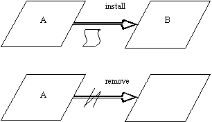
Buhr(1984) contained the concept of abort - Buhr(1990) supersedes this
with the paired concepts of installation and removal. The convention in
the figure above shows a machine being installed based on a blueprint,
represented as a scroll (we omit this scrolled icon from now on). The second
part of the figure shows a machine being removed, which is equivalent conceptually
to aborting a task.
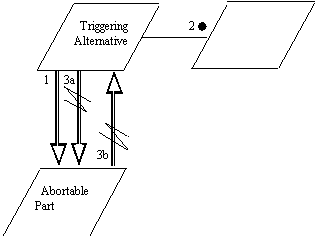
Above, the triggering alternative installs the abortable part, then
makes an entry call (2) and blocks. (The dot at 2 is a Buhr convention
indicating a potential waiting.) If the entry call completes, the triggering
alternative removes the abortable part (3a). If the abortable part completes
first, the abortable part aborts the triggering alternative (Ada 9X calls
for the triggering statement to be aborted, and the sequence of statements
of the triggering alternative not be executed) (3b).
This diagram makes explicit the two-sided nature of the asynchronous
transfer of control - depending on whether the abortable part or the triggering
statement complete first, either may end up aborting the sequence of statements
or the triggering statement of the other.
However, the diagram implies concepts that do not exist in the language
construct. In Ada 9X, there is no sense in which the triggering alternative
creates the abortable part. In a more general sense, the triggering alternative
is not intended to be an independent task. Also, the abortable part can
only abort the triggering statement when the abortable part completes -
the diagram implies more symmetry than exists in the language construct.
As an alternate way to model asynchronous transfer of control, Buhr's conventions for exception-handling can be used.
Buhr (1990) calls for a hooked line to be used to indicate propagation
of exceptions and alarms. An alarm handler is represented as a rectangle:

Using this convention, an asynchronous transfer of control can be shown:
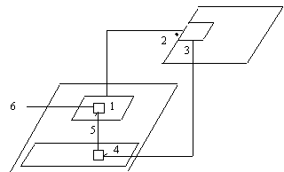
In the figure above, both the triggering alternative (1) and the abortable
part (4) are shown as parallelograms inside a task. First, the triggering
statement of the triggering alternative is made. In this case, an entry
call is placed to another task (2). While the triggering statement waits,
the abortable part is running. So when the accept statement completes,
a signal is generated (3) that interrupts the abortable part (4). The abortable
part immediately transfers control to the statements following the triggering
statement in the triggering alternative (5). This is where the handling
really takes place - the triggering alternative may make more calls outside
the task (6).
This representation is a fairly complex and not very accurate portrayal
of what is happening. A normal occurrence, the completion of an accept
statement, is represented here as an exception, as it is necessary to suggest
the interruption in the control of the abortable part. Yet this is deceptive,
as the programmer cannot write a handler for an interrupt in the abortable
part.
There is another issue with the above representation. The relation between
the final part and the triggering alternatives is not made clear. There
is no way to gather from the diagram that the two inner parallelograms
are part of a single select statement. Nor is there a way to recognize
the construction as being an asynchronous transfer of control as opposed
to a normal exception propagation.
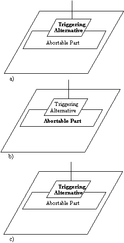
We propose the following convention:
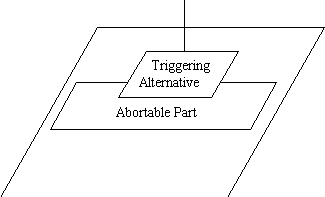
Note that overlap is used to indicate a form of precedence. The triggering
alternative can interrupt and abort the abortable part. Overlap was chosen
as it:
ï suggests the triggering alternative as interrupting the abortable part
ï establishes an association between the triggering alternative and the abortable part of the select statement.
ï can be drawn easily.
ï does not conflict with other Buhr conventions
The non-terminated vertical line is assumed to connect up to an entry
call. In figure 6.13, the different stages of a task using an abortable
part are shown.
In a), the triggering alternative places an entry call. In Figure b),
the entry call has not returned, so the abortable part begins running.
In c), the entry call has returned, and the abortable part is aborted.
Control has gone to the triggering alternative.
Below, a textual and a graphic representation are compared:
loop
select
TERMINAL.WAIT_FOR_INTERRUPT;
PUT_LINE("Interrupted");
in
PUT_LINE("-> ");
GET_LINE(COMMAND, LAST);
PROCESS_COMMAND(COMMAND(1..LAST));
end select;
end loop;
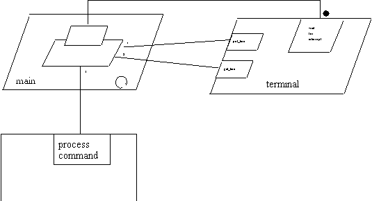
The triggering alternative waits for an interrupt from the terminal.
At the same time, the abortable part puts and gets the command line to
and from the terminal, and processes the command received. The circular
arrow indicates that the main task is persistent and will continue to loop.
The example given in the AARM treats command processing as a procedure.
In many multi-tasking systems, shells spawn tasks or processes to perform
the work of the command. In Ada 9X, the textual code and its visual representation
might be:
loop
select
TERMINAL.WAIT_FOR_INTERRUPT;
PUT_LINE("Interrupted");
in
declare
SHELL: COMMAND_INTERPRETER;
begin
PUT_LINE("-> ");
GET_LINE(COMMAND);
SHELL.EXEC(COMMAND);
end
end select
end loop
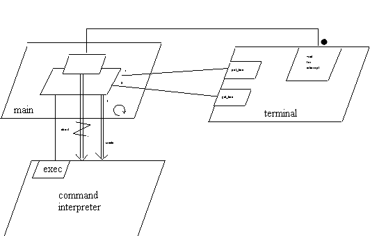
Above, note that a command task is created on every loop through the
shell. In the event that the abortable part is interrupted, the command
task will be aborted. This happens automatically as a result of the abort
of the sequence of statements in the abortable part. We explicitly represent
this as a removal arrow originating from the triggering alternative.
An abortable part can also be interrupted by a delay statement. This
allows for code to be written that will be interrupted if it exceeds some
time boundary, as in the example shown below (AARM 9.7.4.11;2.0) :
select
delay 5.0
PUT_LINE("Calculation doesn't converge");
then abort
HORRIBLY_COMPLICATED_RECURSIVE_FUNC(X,Y);
end select;
The visualization of this is analogous to the visualization shown before
of an entry call statement. Instead of waiting for an accept statement
to complete, the triggering statement is waiting for a timer to expire.
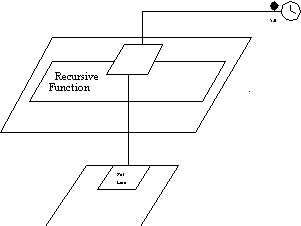
The clock symbol used here is consistent with Buhr (1990) notation.
When the timer expires, control will transfer to the triggering statement,
which in this case will put a message out to the terminal.
In systems with many time-outs, it is easy to imagine a short-hand emerging,
in which the triggering statement itself contains the clock symbol:

The intended meaning is that of figure 6.16: when the timer runs out, if the abortable part is still running, abort the sequence of statements in the abortable part and transfer control to the triggering alternative.
Given this new convention, it is worth considering how the visual representation
of asynchronous transfer of control can contribute to the system design
process. As Buhr (1990) points out, the visual can sometimes aid in capturing
the essence of a problem that may be otherwise be represented as many lines
of disparate code. One point of visual representation is to allow a concept
to be represented in such a way that it can be taken in instantly. Another
point specific to system design is to allow the multiple potential sequences
of interaction to be walked through and discussed. Much of the utility
of system design notations come from the work that a team can do with a
shared convention and an interactive visual medium such as a whiteboard.
This kind of conversation often involves using the diagram as a map, and
sequentially stepping through an event and its implications on the process
it directly touches, along with the ripple effect on other dependent or
synchronized tasks. In a sense, in early design stages, the diagrams are
used as the basis for informal simulations of the working system. Buhr
proposes the use of graphic user interfaces as an alternate way of doing
these simulations. With the proper design tools, and with the design diagrams
linked with underlying code, the hope is that time-based systems design
can benefit in the same way as other design fields have benefited from
CAD tools.
With this in mind, we consider a more complicated instance of asynchronous
transfer of control. In the example of figure 6.15, a new task is created
by an abortable part. It is certainly possible that a task that is created
may itself include an asynchronous transfer of control. It may not be immediately
obvious in a system with many lines of code how deep this cascading of
asynchronous transfers of control goes. Yet the end effect is a set of
tasks that are closely linked together - the completion of an accept statement
on any of the blocked entry calls will affect all the tasks at a deeper
level of the cascade.
This sort of cascade can be represented in the following way:
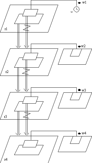
The first robot (r1) creates r2, which in turn creates r3, which in
turn creates r4. Each robot contains an asynchronous transfer of control
with a corresponding waiting place (w1, w2, w3, w4). In the event that
any triggering statement completes, the task dependent on the abortable
part will be aborted. This is shown through a set of abort arrows from
the triggering alternative to the created tasks.
In the event that a task is aborted, all tasks dependent on it are also
aborted. If, say, the accept completes at w2, then not only will the abortable
part of r2 be aborted, but r3 will also be aborted. The abort of r3 will
in turn cause the abort of r4.
So, from this diagram it becomes clear that, depending on which triggering
statement completes first, a chain reaction of aborts is possible. It is
also clear, that no matter what else happens, r2, r3, and r4 will be aborted
when the timer at w1 expires after 5 seconds.
For the system designer, the extension to MachineChart notation shown
here makes it possible to visually trace the ramifications of a design
that uses asynchronous transfer of control.
While a protected record is a well-understood concept in operating system
design, the requeue of Ada 9X is not so universal.
The requeue is allowed only in an entry body or an accept statement.
It can be used to complete the execution of the entry or accept statement,
by redirecting the original entry call to a new entry.
This is very different from calling another entry from within the body
of an entry. Buhr notation allows for a button, the equivalent of an entry,
to fire off another externally visible button. The diagram must show the
line coming out of the interior of the task and invoking the entry from
the outside, as in the following diagram:
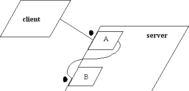
Figure 6.19. A invokes B and deadlocks.
Note that the client is waiting on A, and A is waiting on B. Since,
in this example, A and B are part of the same task, a deadlock will occur.
This is visually apparent - there is an obvious cycle in what amounts to
a resource dependency graph.
There exists no convention for requeue in Buhr notation, but it is obvious
we must differentiate it from the above situation. Since the call from
the client is essentially being redirected, we show the call bouncing from
one entry to another entry. In this case it bounces to another entry in
the same task.
While Buhr's convention calls for lines to be undirected, with flow
indicated by additional dataflow arrows, we propose that Requeue be shown
with a directed arrow to emphasize the redirection aspect of the command.
Requeue either has no parameters or passes through the existing parameters,
so dataflow arrows are unnecessary.
In analyzing a diagram for resource loops, the Requeue command should,
in the example shown, translate to the client waiting on B, not A waiting
on B. From a resource management perspective, this is the correct way to
look at the problem. From an implementation perspective, a lock may still
be held on A if B is in another task or another protected record. But A
is not waiting on B. Since a requeue is probably part of some conditional
logic, deadlock detection algorithms will have to traverse alternate paths
from this diagram, one for the case of a normal execution of A, another
for the case of a requeue.
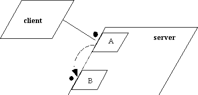
Figure 6.20. Requeueing from A to B.
Requeue can be used to suspend a caller from within the server task.
The following is an Ada outline from the Map Specification (S9.7.1) which
demonstrates the use of requeue to allocate print jobs to multiple printers.
package PRINTER_PKG is
        task PRINTER_SERVER is
                entry PRINT(FILE_NAME : STRING);
        end PRINTER_SERVER;
end PRINTER_PKG;

package BODY PRINTER_PKG is
        type PRINTER_INFO is record ...;
        protected type PRINTER is
                procedure START(FILE_NAME : STRING);
                entry DONE;
                procedure INITIALIZE(INFO : PRINTER_INFO);
        private
                procedure HANDLE_INTERRUPT;
        record
                INFO : PRINTER_INFO;
                PRINTER_BUSY : BOOLEAN := FALSE;
                CURRENT_FILE : SRING(1..MAX_FILE_NAME);
                POSITION_IN_FILE : NATURAL := 0;
                BUFFER : STRING(1..4096);
        end PRINTER;

        type PRINTER_ID is range 1..NUM_PRINTERS;
        PRINTER_ARRAY : array (PRINTER_ID) of PRINTER;
        PRINTER_INFO : constant array (PRINTER_ID)
                of PRINTER_INFO :=
                        6.6.1. => ...);
        task body PRINTER_SERVER is
                PRT : PRINTER_ID;
        begin
                for I in PRINTER_ID loop
                        PRINTER_ARRAY(I).INTIALIZE(PRINTER_INFO(I));
                end loop
                loop
                        select
                                for I in PRINTER_ARRAY'RANGE
                                        PRINTER_ARRAY(I).DONE;
                                        PRT := 1;
                        end select;
                        select
                                accept PRINT(FILE_NAME : STRING) do
                                        PRINTER_ARRAY(PRT).START(FILE_NAME);
                                requeue PRINTER_ARRAY(PRT).DONE with abort;
                                end PRINT
                        or
                                terminate
                        end select;
                end loop;
        end PRINTER_SERVER;
end PRINTER_PKG;
This can be represented with MachineChart notation extended with the
requeue arrow: 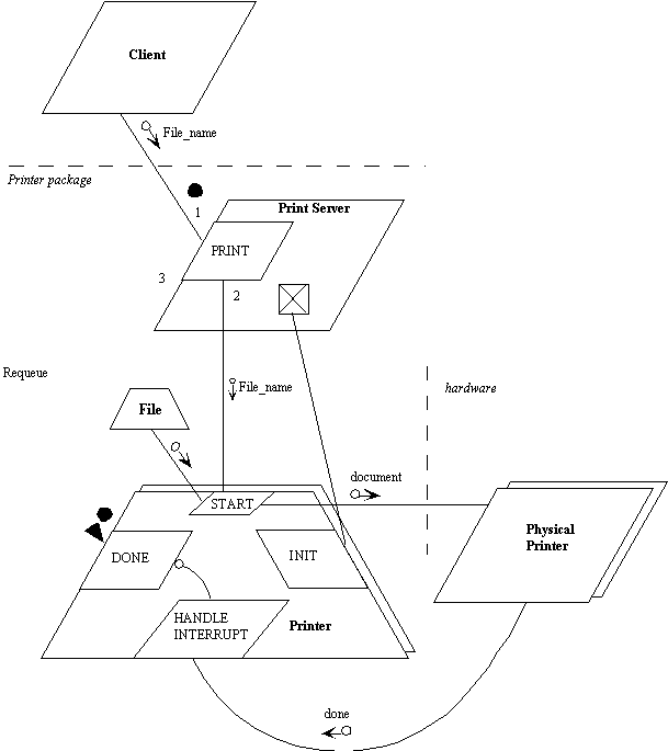
First the client calls the only visible routine to him, PRINT. PRINT
calls the START procedure of the protected type of an available printer,
and then puts the caller onto DONE queue of the protected type using requeue.
When the print job is done, the barrier on the DONE entry will be true,
and the client will resume. Requeue in this case is being used to load
balance.
Note that the physical printer can be represented on the diagram. Most
probably, the printer will raise a signal on completion of printer or detection
of an error; this is shown here as a link from the hardware device to the
interrupt handler.
A file name is passed to the protected type PRINTER. The procedure START
will be responsible for reading from the file and formatting the data.
The file is represented as a protected record.
The first reaction to figure 6.21 is one of disbelief at the complexity
of it. Yet there is nothing extraneous on the diagram. By creating an alternate
description of the problem from that of source code, the hope is that programmers
and testers can gain a better understanding of the intricacies of time-domain
problems.
Reuse in Ada is accomplished through generics. We look at how generics
can be represented visually,
Buhr (1990) invents a template icon, that is to be thought of as a partially
unrolled blueprint. It represents a set of building plans. A line from
a template to a box represents installation. Customization parameters are
shown as dataflow arrows along the install arrow. In the example below,
a template STACK is used to construct a stack package. The type of the
element in the stack, ITEM, can be customized, as can the upper limit on
the size of the stack.
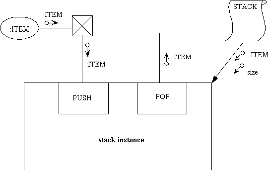
Figure 6.22. Stack instantiation from a template.
The diagram is not complete; there would normally be exception conditions
raised by PUSH and POP after comparison of an internal stack size counter
with either 0 or the customized size.
Ada 9X allows the ability to pass instantiated packages into generics
as parameters. This adds a lot of power to the Generics, and makes the
diagramming of Generic relations more challenging. Here is a textual example
from the Ada 9X mapping specification.
generic
        type FLOAT_TYPE is digits <>;
package GENERIC_COMPLEX_FUNCTIONS is
        type COMPLEX is
                record
                        REAL : FLOAT_TYPE;
                        IMAG : FLOAT_TYPE;
                end record;

        function "-" (RIGHT : COMPLEX) return COMPLEX;
        function "+" (LEFT, RIGHT : COMPLEX) return COMPLEX;
        ...
end GENERIC_COMPLEX_FUNCTIONS;

generic
        with PACKAGE COMPLEX FUNCTIONS is
                new GENERIC_COMPLEX_FUNCTIONS(<>);
package GENERIC_COMPLEX_MATRIX_OPERATIONS is
        type COMPLEX_MATRIX is
                array(positive range <>, positive range <>)
                        of COMPLEX FUNCTIONS.COMPLEX;
        function "*" (LEFT : COMPLEX_FUNCTIONS.COMPLEX;
                            RIGHT : COMPLEX_MATRIX)
          return COMPLEX_MATRIX;
end GENERIC_COMPLEX_MATRIX_OPERATIONS;

package SHORT_COMPLEX_PKG is
        NEW GENERIC_COMPLEX_FUNCTIONS(SHORT_FLOAT);
...
package SHORT_COMPLEX_MATRIX_PKG is
        new GENERIC_COMPLEX_MATRIX_OPERATIONS(SHORT_COMPLEX_PKG);
The Matrix package takes a complex function package as a parameter.
This means that first GENERIC_COMPLEX_FUNCTIONS is instantiated, and then
the Matrix package is built with this as a parameter. Within the Matrix
package the types and functions of the package that has been passed in
can be accessed.
In order to visualize this, we go through a few different representations,
before settling on a notation that is different from Buhr's generic notation.
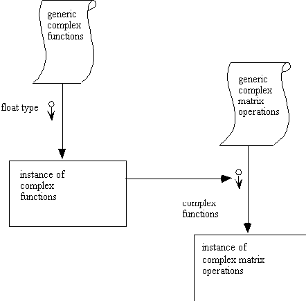
In the following diagram, Buhr notation is used. Since the typing and
binding of parameters in Buhr diagrams take place in small arrows with
circular tails, there is no obvious way to bind the result of an operation
to the formal parameter of another. Shown below is an attempt at this by
drawing an arrow from a package instance of GENERIC_COMPLEX_FUNCTIONS to
the formal package parameter of generic complex matrix operations.
In the following diagram, a convention is set up to explicitly bind
actual parameters to formal parameters by drawing arrows that meet at a
diamond-shaped node. The binding arrow is shown as a dotted line.
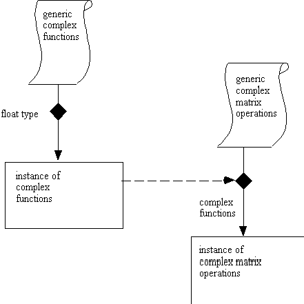
In looking at the above diagram, it is bothersome that it does not represent the syntax of Ada. In Ada, the generic takes a parameter very much like a function takes a parameter. Then the generic is instantiated with the new keyword. As one step toward this kind of representation, we create a new convention for instantiation, using an arrow with an unfilled head as below:
The next step is to redraw the previous diagram using the instantiation
arrow, and feed generic parameters into the templates for binding before
instantiation:

The above is more like a data flow diagram than a MachineChart diagram.
However, it seems to model better what is happening in the Ada language.
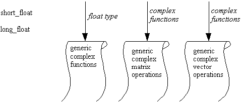
If this convention is used as part of a Case tool, a series of templates
with their corresponding formal parameters might be arranged as part of
a graphic menu. By combining these templates with instances and primitive
types, it would be possible to fully specify a set of instantiations. Such
a menu might look like this:
The following is a continuation of the textual example above, also taken from the Ada 9X Mapping Specification:
generic
        type GROUP_ELEMENT is private;
        IDENTITY : CONSTANT GROUP_ELEMENT;
        with function OP(LEFT, RIGHT : GROUP_ELEMENT)
                return GROUP_ELEMENT;
        with function INVERSE(RIGHT : GROUP_ELEMENT)
                return GROUP_ELEMENT;
package GROUP_SIGNATURE is end;

generic
        with package GROUP is new GROUP_SIGNATURE(<>);
function POWER(LEFT : GROUP.GROUP_ELEMENT; RIGHT : INTEGER)
        return GROUP.GROUP_ELEMENT;

function POWER(LEFT : GROUP. GROUP_ELEMENT; RIGHT : INTEGER)
        return GROUP.GROUP_ELEMENT is
        result : GROUP.GROUP_ELEMENT := IDENTITY;
begin
        for I in 1 .. abs RIGHT loop
                result := GROUP.OP(RESULT, LEFT);
        end loop;
        if RIGHT < 0 then
                return GROUP.INVERSE(RESULT);
        else
                return RESULT;
        end if;
end POWER;

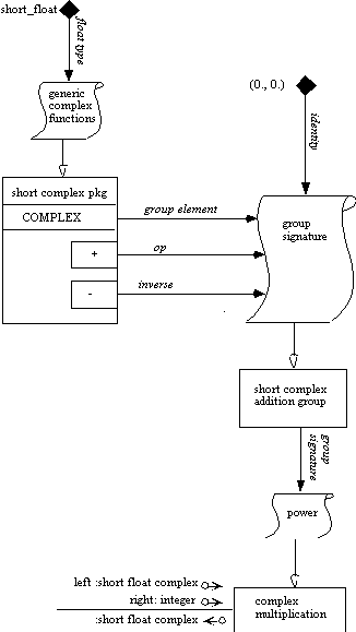
package SHORT_COMPLEX_ADDITION_GROUP is
        new GROUP_SIGNATURE(SHORT_COMPLEX_PKG.COMPLEX,  IDENTITY => (0.0, 0.0),
        OP => SHORT_COMPLEX_PKG."+",
        INVERSE => SHORT_COMPLEX_PKG."-");

function COMPLEX_MULTIPLICATION is
        new POWER(SHORT_COMPLEX_ADDITION_GROUP);
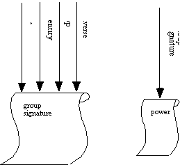
In order to visualize the above program, it is necessary to create representations for the group signature package as well as for the power generic function:
It is also necessary to show more detail on the contents of the instantiation
of the short complex package. We choose to use a notation most similar
to Rumbaugh's (1991) notation, which has the advantage of making the COMPLEX
type visible for connections.

The following represents the instantiation of the power function:
System design is often done collectively on white boards. The results
of this design process are often lost in the translation to textual code.
Buhr's MachineChart notation is a rigorous way of capturing system diagrams.
It also has the potential to be used in generating code from diagrams.
And it certainly helps in the detection of common system problems such
as deadlock, because cycle detection from a visual graph is easier than
cycle detection from text.
Buhr's concept of a reactor works as a representation of Protected Records
in Ada 9X. A simple extension to the notation allows requeueing to be modeled.
Asynchronous transfer of control also can be successfully grafted on to
the notation. The 9X extensions to Generics, however, suggest the possibility
Buhr notation for generic instantiation needs a revamp in order to handle
the bindings of packages to generic formal parameters. Or, in a deeper
way, it suggests that perhaps Generics are best represented textually -
that Generics are based on a naming convention, while most other components
of system design deal with places.
System design seems to go with graphic representation. The place-like
nature of processes lends itself to something akin to architecture in a
topological domain. It is something to keep in mind as we now turn to understanding
the limits of the visual.